RO membrane performance losses – rising differential pressure, declining flux, and early replacement – almost always trace back to decisions made before the membrane was selected or installed. Understanding how RO membranes actually work is the foundation for avoiding those failures.
Reverse osmosis is a pressure-driven membrane process that reliably removes Total Dissolved Solids (TDS) and heavy metals from industrial water. Reverse osmosis reduces bacteria and viruses, which is why pharma production and electronics manufacturing use the process when water purity directly affects yield or compliance.
Boiler feedwater service and water reuse depend on RO performance, because modern RO membranes deliver high recovery with lower energy demand. Effective pre-treatment, including sediment filtration and carbon filtration, protects the RO membrane from fouling and scaling, preserving stable plant output throughout the service life.
Osmosis vs. Reverse Osmosis: What’s the Difference?
A semi-permeable membrane is a barrier that allows water molecules to pass but holds back most dissolved salts in source water. When lower-salinity water sits beside higher-salinity water, osmosis drives flow toward the more concentrated side.
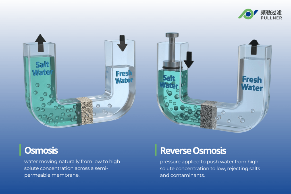
The semi-permeable membrane restricts dissolved solids while allowing water to pass, so the concentration gradient determines which way net flow moves. As water shifts, pressure builds until the chemical potential is balanced and osmotic pressure builds across the membrane. Industrial water filtration systems use this behavior to manage water quality.
Reverse osmosis begins when the applied pressure on the high-TDS side exceeds the natural osmotic pressure inside an RO system. Under reverse flow, the RO membrane forces water toward the cleaner side.
Most salts and dissolved contaminants remain on the pressurized side, so the reverse osmosis membrane produces permeate with significantly lower TDS for industrial water treatment. For example, well water can enter an RO stage at several bars of pressure, then exit as low-conductivity water for boiler feed use.
| Factor | Osmosis | التناضح العكسي |
|---|---|---|
| Flow direction | Water moves from a lower solute concentration to a higher solute concentration | Water moves from a higher solute concentration to a lower solute concentration |
| Pressure source | Natural osmotic pressure drives movement | External pressure drives movement |
| Membrane role | A semi-permeable membrane allows water through and restricts dissolved salts | A semi-permeable membrane allows water through and rejects most dissolved salts |
| Contaminant separation | Separation is limited because flow follows the natural concentration gradient | Separation is strong because pressure forces water through the membrane |
| Industrial purpose | Explains the natural movement across a membrane | Produces lower-TDS water for process use |
| Example | Water moves toward the more concentrated side of the membrane | Applying 10 to 15 bar of pressure to brackish water pushes water through the membrane and leaves most dissolved salts behind |
Inside an RO Membrane: Materials and Structure
Inside an RO membrane, manufacturers use a thin-film composite membrane with a tough polyester backing, a porous support layer, and an ultra-thin polyamide skin. Manufacturers form those layers into spiral-wound elements to maximize active membrane area in a compact footprint.
Thin‑Film Composite (TFC) Construction
An industrial RO membrane uses a thin-film composite membrane with distinct layers that control transport and separation. A polyester backing gives the structure mechanical stability during reverse osmosis duty.
A microporous polysulfone support provides a low-resistance flow path, enabling water to move through the structure under pressure. At the surface, a sub-micron polyamide film rejects dissolved salts and controls separation performance. The backing reaches hundreds of microns in thickness, but the support layer remains much thinner to preserve flow efficiency.
Layered RO construction combines strong rejection with practical throughput in industrial water treatment. The polyamide barrier can reduce the concentration of monovalent ions and maintain stable water quality under pressure.
Polyamide chemistry balances permeability with selectivity, but free chlorine can damage the membrane surface. Manufacturers tune charge or hydrophilicity to improve fouling resistance across changing source water conditions.
Spiral‑Wound Element Design
Industrial elements use TFC membranes arranged as flat leaves inside a compact housing. Each leaf contains two membrane sheets sealed on three sides, with a permeate spacer between them to create an internal channel.
Plastic feed spacers sit between adjacent leaves and the assembly wraps tightly around a perforated tube. An outer fiberglass or plastic shell helps the element tolerate pressure inside industrial reverse osmosis systems.
At the inlet, feed water enters the element under pressure and moves along spacer channels from one end to the other. As water flows across the surface, water passes through a membrane into permeate channels and spirals inward toward the center tube.
The unit collects treated water there, while the reject (brine) exits separately. High active area and standard dimensions make the design common across large installations.
How the RO Membrane Separates Contaminants
Inside the dense polyamide layer, water dissolves into the film, then diffuses through it before emerging as permeate. The membrane can remove impurities from water because most dissolved salts and metals have low mobility or unfavorable charge interactions. Larger organics and microorganisms remain on the feed side.
Molecular‑Scale Separation Mechanism
In the reverse osmosis process, the active polyamide layer behaves like a dense polymer matrix instead of an open screen with through-pores. Under pressure, water permeates a membrane when it dissolves into the polymer surface on the feed side.
The polymer then drives diffusion across the film, and permeate emerges on the low-pressure side. Engineers use this model to explain how reverse osmosis works at the molecular scale. Hydrated ions and larger organic species exhibit very low solubility in the polyamide matrix, so their movement remains far slower than water transport.
Charged solutes interact with the surface chemistry, which limits passage and helps separate impurities from water. As a result, the membrane rejects dissolved salts, heavy metals, and many organic compounds before they enter the permeate. Technical teams describe this outcome as reverse osmosis separation rather than simple screening.
Permeate and Concentrate Streams
In a reverse osmosis water system, water enters as the feed stream, carrying dissolved solids and other contaminants. Under pressure, part of that flow crosses the active layer and becomes permeate, which operators collect as low-TDS RO water.
The remaining portion stays on the feed side, where contaminants from the water continue to accumulate. Along the element, the split remains continuous, so treated flow and concentrate form simultaneously.
As the channel length increases, the non-permeated stream grows stronger and exits as brine or retentate. Operators measure salt rejection as the percentage removed, then review permeate conductivity or TDS to confirm the quality of the water produced.
The recovery rate compares permeate flow with inlet flow and shows how efficiently the unit uses the water supply. Over time, those readings help plants match output to specific water treatment needs and spot declining membrane condition.
Cross‑Flow Design: How RO Limits Fouling
Cross-flow keeps liquid moving parallel to the membrane face instead of forcing nearly all fluid straight through the media. In dead-end service, solids build rapidly at the surface and resistance rises fast.
In RO duty, shear at the interface helps sweep suspended matter away before a dense cake can form. The same motion reduces concentration buildup near the film, so the system slows fouling and supports steadier separation across the active area.
Engineers set channel velocity, spacer geometry, and staging to maintain stable hydraulics through the vessel’s length. Higher recovery can improve water use efficiency, but rising surface salinity increases the risk of fouling.
For that reason, industrial reverse osmosis systems balance recovery with pressure drop and cleaning intervals. Proper hydraulic design maintains stable flux, limits scale formation, and extends element service life.
Operating Parameters That Make the Membrane Work
RO performance depends on applied pressure, temperature, feedwater salinity, and flow conditions. Stable control matters because these variables govern permeate flux, salt rejection, energy demand, and membrane surface fouling or scaling rates.
Pressure and Flux
Transmembrane pressure is the effective pressure difference between the feed water and permeate sides. Engineers calculate it from the average feed-side pressure minus the permeate pressure.
Applied pressure must exceed osmotic forces to drive water through a semipermeable membrane. Higher effective pressure increases permeate flux within the membrane’s design limits. Designers set target flux from membrane type, feed water quality, and expected fouling rates.
Permeate flux is central to membrane sizing and plant evaluation. Low pressure reduces production and the efficiency of reverse osmosis water filtration.
Excessive pressure can compress the RO membrane, reduce permeability, increase energy use, and damage downstream components. Operation within the recommended range preserves treated water output and membrane life.
Temperature and Water Chemistry
As water temperature rises, viscosity drops, and the RO membrane polymer becomes more permeable. Consequently, the water flows faster, increasing permeate flux at the same applied pressure.
Operators use standard reference temperatures, often 77° F, to correct flux readings and distinguish genuine fouling from simple thermal effects. Exceeding the maximum allowable temperature accelerates membrane aging or risks damage in industrial reverse osmosis systems.
Higher feedwater TDS increases osmotic pressure, reducing the net driving force for permeation and requiring higher pump pressure to maintain flux. Hardness ions, barium, strontium, silica, and organic matter influence scaling and fouling risk.
Plants adjust antiscalant dosing, pH, softening, and organic load to control these effects. Such water treatment processes help protect system performance and maintain quality water output while keeping cleaning intervals reasonable.
Pretreatment: Protecting the RO Membrane in Industrial Plants
The ultra-fine polyamide layer of an RO membrane is highly sensitive to fouling from suspended solids, colloids, organics, or biofilm.
Exposure to free chlorine and other oxidants can damage the surface. Insufficient pretreatment quickly increases differential pressure, reduces flux, and forces more frequent cleaning or early membrane replacement.
Pretreatment steps include multimedia or cartridge filtration to lower silt density index, activated carbon or chemical dechlorination to remove oxidants, and softening, antiscalant dosing, or pH control to limit scaling salts.
Microfiltration or ultrafiltration may be applied for highly turbid or biologically active feedwater. Together, these pretreatment steps protect the RO membrane, maintain flux, reduce cleaning frequency, and support stable operation across industrial plants.
Fouling, Scaling, and Cleaning: Troubleshooting RO Membranes
Fouling and scale deposits reduce RO performance over time. Biofilm can reduce flux, increase pressure drop, or degrade permeate quality. Targeted chemical cleaning, along with operation within design limits, restores output and supports more stable long-term performance.
Common Fouling Mechanisms
Fouling begins when solids or colloids deposit on the membrane surface. Organic material from oils, humic substances, or biological matter can form stubborn films on the membrane surface, while microbial growth can form biofilms under nutrient-rich conditions.
Scaling occurs when salts precipitate from hard water or other difficult water sources. Surface water and reuse applications often combine multiple mechanisms in the same train. Plant data reveals the dominant problem over time. Most fouling lowers the normalized permeate flux at the same pressure and temperature.
Particulate deposits and biofilm often raise differential pressure across the vessel, while severe scale can weaken rejection and increase permeate conductivity. Teams that use trend data can narrow the cause, plan cleaning steps, and protect stable operation.
Cleaning and Maintenance
Plants clean RO trains in place with chemistries matched to the foulant. Low-pH cleaners dissolve mineral scale, while high-pH blends remove organic deposits or biofilm.
Approved treatments must be compatible with the membrane, as membranes are designed for defined chemical exposure limits. Operators isolate the train, circulate a heated solution at low pressure, allow soak time, and fully rinse before service resumes.
Plants trigger cleaning when normalized flux falls or differential pressure rises beyond set limits. Permeate conductivity can signal declining separation. Cleaning strength depends on feed chemistry and the plant’s specific water treatment needs.
Maintenance teams stay within supplier limits for pH, temperature, contact time, and flow. Documented cleaning history helps identify pretreatment gaps and refine future cleaning intervals.
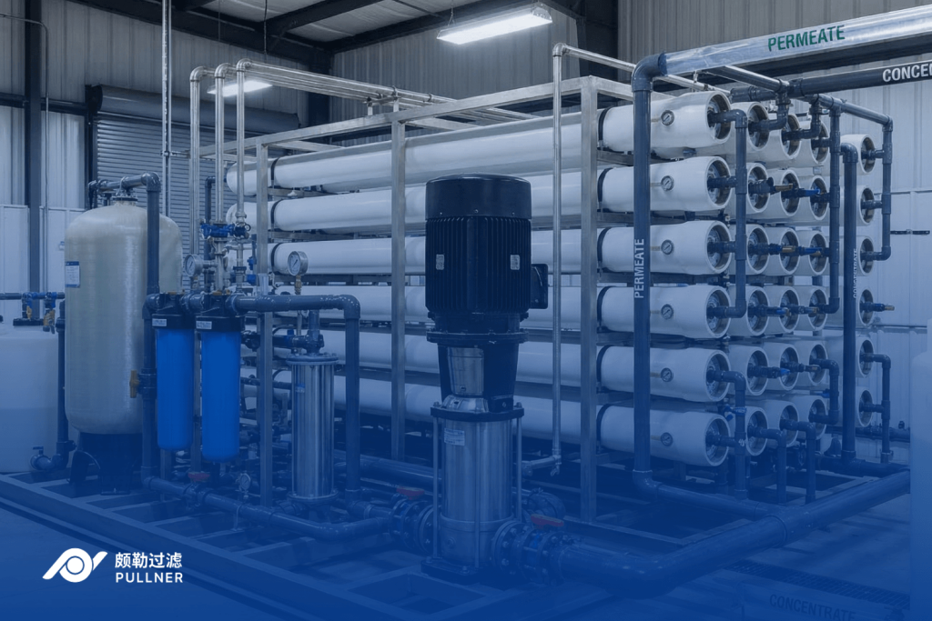
Industrial Design Considerations: From Theory to Real Plants
Engineers apply reverse osmosis technology to match element type with feed salinity, operating pressure, and target flux. Brackish water systems typically use lower-pressure elements, while seawater applications require stronger construction and tighter operating margins.
Product quality requirements shape the layout. A single-pass train may suit general process use, but a two-pass arrangement is often preferred for a drinking water system or a high-purity boiler supply. Recovery targets depend on scaling limits and source water chemistry.
Operators verify performance with flow, pressure, and conductivity data from the feed, permeate, and concentrate lines. Those readings show recovery, pressure drop, and salt rejection in real time.
Historical comparisons help teams identify fouling or hydraulic imbalances early. Data review supports chemical control, cleaning schedules, and setpoint changes that keep the plant delivering stable permeate production under steady conditions.
Why Understanding the Membrane Matters
Industrial operators face constant pressure to maintain stable water quality, control operating costs, and avoid unplanned downtime across treatment assets. Understanding membrane behavior across osmosis, pressure, fouling, and pretreatment helps buyers interpret plant data accurately and resolve performance losses more quickly.
Pullner Filter supplies RO pretreatment cartridges, including high-flow, pleated, and membrane filter elements, matched to process chemistry and operating conditions, backed by ISO 9001 quality management and 100% factory testing. Their in-house lab provides PMI pore analysis, SEM verification at 3nm resolution, and ICP-MS testing, delivering documentation that supports change control and validation reviews.
Pullner’s engineering team provides up to two free sample cartridges – customers cover shipping – so teams can validate pretreatment performance before committing to a full purchase. الاتصال بفلتر بولنر to review your RO pretreatment or process requirements and request a consultation on the most suitable cartridge configuration.
How Does a Reverse Osmosis Membrane Work FAQs
How long do industrial RO membranes typically last before replacement?
Industrial RO membranes last three to seven years. Lifespan depends on feedwater quality, pretreatment effectiveness, operating conditions, and the effectiveness of monitoring and cleaning to manage fouling and scaling.
Can RO membranes remove all microorganisms, including viruses, from industrial process water?
RO membranes achieve high rejection of bacteria and many viruses because of their dense structure, but they are not certified as sterilizing barriers. Critical applications often combine RO with disinfection or a final 0.2 µm membrane filter for guaranteed microbial control.
What is the difference between brackish water RO and seawater RO membranes?
Brackish RO membranes suit lower-salinity feeds and operate at moderate pressures. Seawater RO membranes handle much higher TDS, require higher pressures, and have different permeate flux and energy consumption characteristics.
العودة إلى الأعلى How Does a Reverse Osmosis Membrane Work?