
A coalescing filter separates fine droplets from gas or another liquid by merging them into larger drops that leave the process stream. Unlike a particulate cartridge, it targets a dispersed liquid phase rather than relying only on pore size to retain solids. The device handles suspended moisture, oil mist, and other entrained liquids that pass straight through ordinary gravity equipment.
Dissolved compounds remain within the continuous phase, so operators must identify whether contamination exists as droplets, vapor, or solution before choosing equipment. Performance also depends on stable drainage, compatible construction, and controlled velocity through the active material. Incorrect specification can increase resistance, permit liquid carryover, or expose components to damaging chemistry.
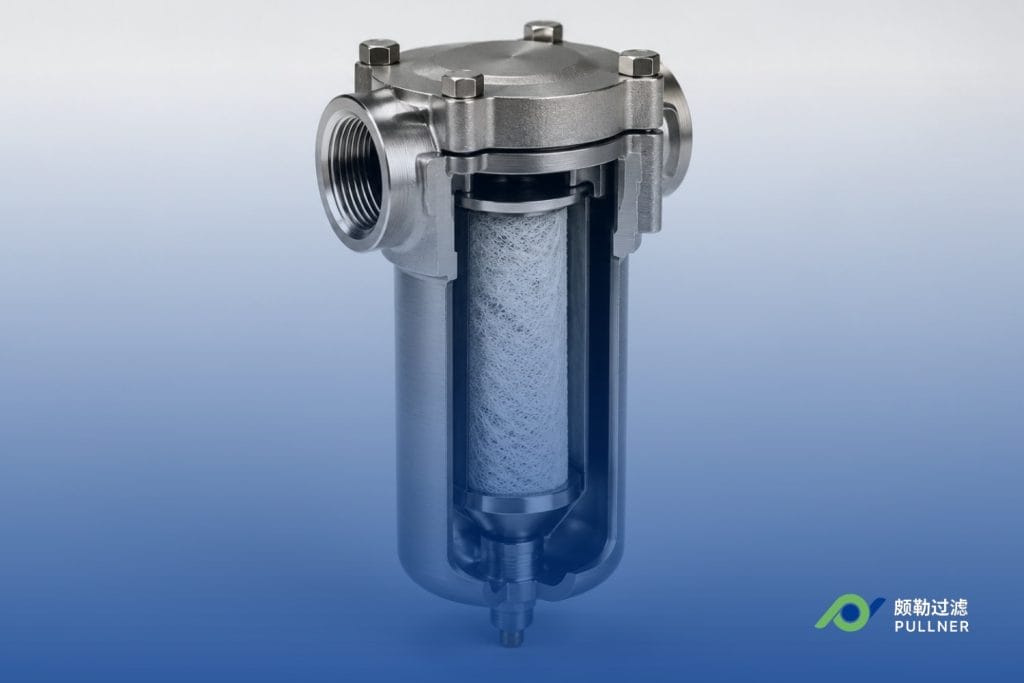
How Coalescing Filtration Works
During coalescing filtration, fiber spacing, surface behavior, and controlled flow create the conditions that let a dispersed liquid leave its continuous phase.
Droplet capture
As fluid enters the coalescer filter, the media brings suspended droplets into contact with tightly arranged fibers through three mechanisms. Interception occurs when a droplet follows the flow path closely enough to touch a fiber. Inertial impaction affects larger droplets that cannot turn with the moving stream, causing them to strike the material. Diffusion moves very small aerosols irregularly until they meet the filter surface, a mechanism that becomes more influential as droplet size decreases.
Coalescence and merging
Captured oil and water droplets spread along suitable fibers, forming thin films that connect with newly collected liquid. Surface energy and wettability determine whether a dispersed phase remains attached long enough to merge instead of returning to the stream.
As the film joins neighboring deposits, coalescence produces drops large enough for gravity or a later separation stage to handle. Pore structure, liquid distribution, and drainage-layer design influence resistance and capture in gas-liquid service.
Drainage and separation
Gravity moves enlarged drops through an unobstructed drainage layer toward a sump. Demisting structures reduce carryover by preventing released liquid from becoming re-entrained in the moving gas. In liquid service, density differences allow the dispersed phase to rise or settle after leaving the coalescing layer.
Performance metrics
Differential pressure and capture efficiency measure coalescing performance against energy demand and outlet quality. Differential pressure is the resistance between inlet and outlet, usually measured while the unit runs at a stated flow.
Micron rating identifies the droplet or particle size associated with a documented test method rather than guaranteeing identical field results. Capture efficiency reports the percentage removed under defined conditions, so engineers must read it alongside velocity, loading, and fluid properties. Rising pressure drop across the filter can indicate accumulated solids, retained liquid, or restricted drainage.
Types of Coalescing Filters
Coalescing filters divide into liquid-liquid, gas-liquid, and compressed-air designs. Pullner manufactures the two process types in-house.
Liquid-liquid coalescers
In liquid-liquid duty, a liquid-liquid coalescer separates one liquid dispersed as small drops within another when the two do not dissolve together. The selected media must attract the dispersed phase, support contact between deposits, and release enlarged drops into a settling zone. Treated synthetic fibers handle combinations of oil and water, hydrocarbons, caustic solutions, and amines. Individual water molecules dissolved within the continuous phase remain unaffected.
Separation depends on density difference, viscosity, surfactants, and interfacial tension, the force acting at the boundary between the two liquids. Because surfactants can stabilize small droplets, variable chemistry may require laboratory or pilot testing before final specification. Polymer and fluoropolymer cartridges have treated stable water, caustic, and amine dispersions in natural gas liquids.
Gas-liquid coalescers
With gas as the continuous phase, a gas-liquid coalescer targets water mist, lubricant aerosol, hydrocarbon condensate, and process-solvent carryover. Fine-depth material provides winding paths that promote contact without relying on a simple screen opening.
Controlled drainage releases collected liquid from the fibers. Vertical orientation can support that movement but cannot compensate for excess velocity or unsuitable outlet geometry. The outlet must keep velocity below the point where droplets become airborne again.
Compressed-air coalescers
Compressed-air coalescers remove oil aerosol and water moisture from pneumatic air downstream of a compressor, and their performance is classified against the ISO 8573-1 purity classes of particles, water, and oil. Connections, pressure ratings, and test standards differ from hydrocarbon and chemical process equipment, so the two are not interchangeable.
Media Construction and Why It Matters
Coalescer construction determines which droplets the material captures, how easily liquid drains, and whether the element withstands the operating conditions.
Core materials and layer design
Inside a typical coalescing filter, a support tube carries the high-efficiency coalescing region, fine-fiber section, and outer drainage material. Depth construction captures aerosols throughout its thickness, while surface material retains contamination near the upstream face.
Glass fibers suit many gas duties, whereas polypropylene, polyester, and fluoropolymers cover selected liquid chemistries. Oil-repelling or water-repelling treatments help certain gas-service packs release collected liquid instead of remaining saturated. Pore progression, fiber diameter, and liquid-spreading behavior must suit the dispersed phase within each element.
Cartridge and vessel designs
Within a pressure-retaining filter housing, replaceable coalescing elements provide the active separation area. A single cartridge can serve lower flows, while larger vessels arrange multiple units around distribution and collection hardware. Internal distributors spread flow among installed elements, and sumps provide space for released liquid. When liquid-liquid and gas-liquid formats are manufactured in-house alongside its wider filter cartridge range, dimensions, end connections, and internal arrangements can follow project requirements.
Chemical and temperature compatibility
Compatibility means construction materials tolerate the fluid, temperature, and exposure duration without swelling, embrittlement, corrosion, or lost surface properties. Engineers should assess fibers, binders, seals, supports, and vessel metallurgy rather than checking only the named medium. Amine concentration, acid gases, aromatic hydrocarbons, cleaning chemicals, and temperature cycles can all change material behavior. The chosen grade must meet the removal target without creating unnecessary resistance.
Sizing and Selection Considerations
Size and select a coalescer using maximum flow, allowable differential pressure, contaminant loading, droplet distribution, construction materials, and expected process conditions.
Flow rate and throughput
Maximum flow determines velocity through the active area and the time available inside the vessel. Excess velocity shortens contact time, raises resistance, and can sweep collected liquid back into the outlet. At very low throughput, parallel cartridges may receive uneven distribution and leave active areas underused. An oversized unit raises capital cost and occupies space without improving the process. Designers work from minimum, normal, and peak throughput rather than an annual average.
Differential pressure
Initial differential pressure establishes the clean baseline at a stated flow, temperature, and fluid condition. Operating measurements then reveal changes caused by solid loading, wetting, viscosity, or blocked drainage. Lower resistance reduces energy demand but cannot establish efficiency on its own. Equipment documentation should specify a change-out limit because acceptable readings differ by construction and duty.
Contaminant loading and droplet sizes
Influent testing should identify liquid concentration, solids content, and droplet-size distribution before engineers select an arrangement. A stated micron value has meaning only when its test conditions and efficiency basis are known. Heavy particulate loading can block fine fibers before they complete their intended service period. A suitable prefilter removes contaminants that would otherwise shorten element life, while bulk separators handle slugs ahead of finer equipment.
Materials of construction and process conditions
Pressure rating, temperature range, fluid chemistry, and corrosion allowance shape the cartridge, seals, internals, and vessel shell. Natural gas service may involve condensate, compressor lubricant, and treatment chemicals, while amine circuits introduce solvent compatibility and foaming concerns. Gas containing hydrogen sulfide requires project-specific metallurgy and seal-material review. Engineers must also supply startup, shutdown, and upset conditions, because these can exceed steady operating values.
Maintenance and replacement intervals
Trend differential pressure against flow instead of replacing cartridges by calendar date alone. A sudden increase may indicate solids, whereas persistently high wet resistance can point to drainage trouble or excessive loading. Inspections should cover seals, supports, drains, instruments, and collected-liquid handling. Planned spares and an isolation procedure support change-outs, and an unexpected shift in outlet quality should trigger sampling before continued operation.
Applications by Industry
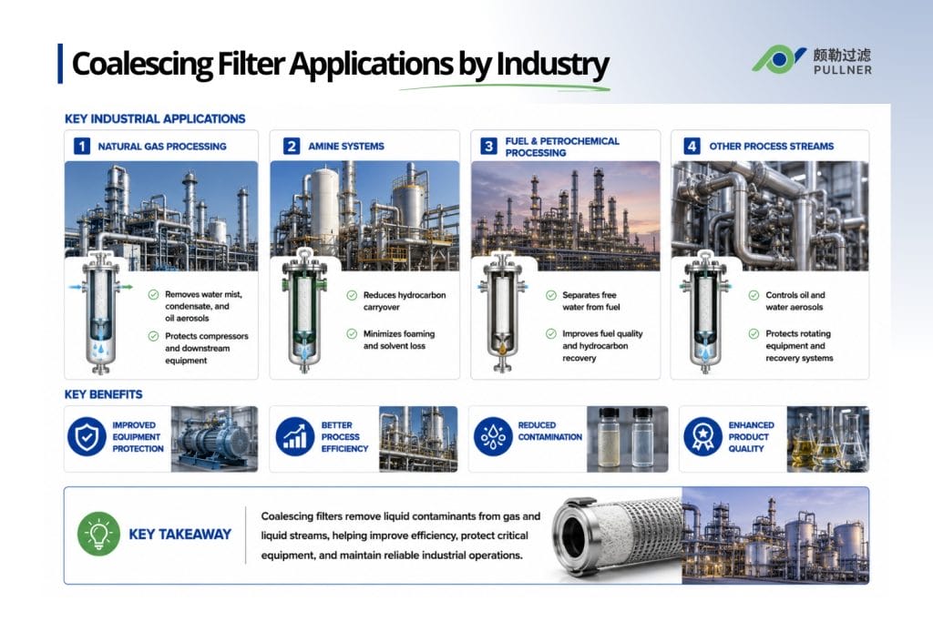
Coalescing filter applications include natural gas treatment, amine protection, fuel polishing, petrochemical separation, condensate recovery, and compressor protection. Pullner produces the liquid-liquid and gas-liquid cartridges used across these process segments in-house.
Natural gas processing
During oil and gas production, wet gas can carry water mist, hydrocarbon condensate, and lubricant aerosols toward compression, dehydration, or metering stages. Reduced carryover gives sensitive equipment a drier feed before those liquids reach rotating components. A gas coalescer placed upstream of the compressor serves this duty, while later units protect molecular sieves or pipeline-quality measurement.
Amine systems
Hydrocarbon carryover entering an amine circuit can contribute to foaming, solvent losses, and impaired gas-liquid contact. Facilities therefore rely on coalescing filters at selected inlet, recovery, or polishing points. Coalescing methods have been applied to immiscible-liquid dispersions in hydrocarbon processing, supporting cleaner circulation without adding another chemical treatment.
Fuels and petrochemical streams
Fuel polishing improves phase clarity before storage, transfer, or a further treatment stage. A coalescer filter can separate free water from fuel or recover hydrocarbons from aqueous streams when the two form distinct droplets. Dissolved compounds require another process, making upstream chemistry and the outlet specification necessary selection inputs.
Other process streams
Where refinery slops, recovered condensate, or compressor discharge carries oil and water aerosols, coalescing filters control entrained liquid before it reaches downstream equipment. In petrochemical service, they protect controls, recovery units, and rotating machinery from direct exposure. Some streams also contain water vapor and sulfur, which other stages must treat separately.
Coalescer Configurations
Coalescer configurations include single-stage cartridges, multi-stage vessels, and inline or retrofit modules, selected according to capacity, liquid loading, solids, and available space.
Single-stage cartridges
For stable feeds, a single-stage unit holds one functional cartridge without additional treatment stages. Upstream equipment must already control bulk liquid and solids, and the incoming load must stay within the specified range to preserve drainage.
Multi-stage vessels
Where feed conditions vary, multi-stage vessels place a prefilter, coalescer, and separator in sequence. Solids remain in the first component, liquid collects within the middle cartridge, and the final section limits carryover. This arrangement provides more control than particulate filtration or gravity settling can deliver independently.
Inline modules and retrofit cartridges
For moderate flows, inline modules provide compact treatment without a large standalone vessel. Retrofit cartridges reuse existing equipment when dimensions, sealing, and hydraulics align. Pullner supplies liquid-liquid and gas-liquid cartridges alongside complete vessel designs. Project drawings must confirm connection style, flow direction, support geometry, and installation clearance before fabrication.
Select a Process Coalescer with Pullner
Pullner Filter manufactures liquid-liquid and gas-liquid coalescer configurations in-house for custom process requirements under an ISO 9001 quality system with 100% factory testing and batch-level traceability. Engineering support covers material selection, prototype development, and laboratory evaluation against supplied operating data.
Submit a completed process datasheet and existing vessel drawings, where available. Pullner’s engineers can evaluate cartridge or vessel requirements, recommend compatible construction materials, and provide up to two free samples for testing, with the customer covering shipping. Request a quote or speak to an engineer about the required separation duty.
FAQs On What is a Coalescing Filter and How does it Work
What is the difference between a coalescer and a separator?
A coalescer prepares fine droplets for removal by merging them, while a separator provides the space and residence time for gravity or inertia to act. Many installations pair both because neither component performs the other’s role.
When do I choose a liquid-liquid coalescer instead of a gas-liquid coalescer?
Use the continuous phase as the decision point. Liquid-liquid equipment handles water dispersed in fuel or another liquid, whereas gas-liquid equipment treats mist carried by natural gas or process gas.
Can coalescing filters remove aerosols and mists?
Yes, provided the performance data cover the expected droplet distribution, velocity, loading, and chemistry. A solids micron rating alone cannot predict liquid-removal performance.
How do I size a coalescing filter for natural gas service?
Calculate active area from the maximum actual gas volume and the manufacturer’s permitted element velocity. Then verify cartridge quantity, drainage capacity, pressure rating, and allowance for upset flow.
Are compressed-air coalescers the same as process coalescers?
No. Compressed-air products address pneumatic air quality under different connections, pressure ratings, and testing standards from hydrocarbon or chemical process units. Match the service classification to the stream before comparing products.
How often should a coalescing element be replaced?
Replacement is driven by differential pressure trended against flow rather than a fixed interval. Equipment documentation should state a change-out limit, since acceptable readings vary by construction and duty.
Back to Top : What is a Coalescing Filter and How does it Work?
 English
  Spanish
  Arabic